KNK Force: Lesson 3
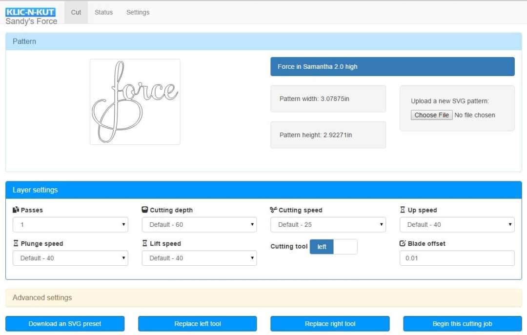
This lesson will cover Layer settings in C3… meaty stuff, so grab a cup of your favorite hot beverage for this one! You might also want to click on the image above and print it in Landscape orientation. That way you can refer to it as you go through the settings and even jot down some notes on the printout.
As previously mentioned, the KNK Force doesn’t have a “force” setting, which is kind of funny, right? Instead it uses a combination of depth and blade tension (this latter setting was covered in Lesson 2). Also, because of Z axis control, you can have progressively increasing depths in multi-pass applications, as well as control the speed along the Z axis. Thus, there are new settings to learn and this lesson presents the names, descriptions, and typical values. But remember that you’ll want to check the settings table before trying out any cuts to make sure what you’re using seems in line with the materials you’re planning to cut.
The Passes setting, which can be set from 1 to 20, controls the number of repeats on any individual path before the blade or tool moves to the next path.
This is an important feature in many applications because having the blade or tool work its way through a material yields a higher quality product. The blade or tool also will remain in the down position during the repeats, which is better than having the blade or tool start over after completing an entire project.
Some examples where more than one pass is recommended:
- Cutting thicker denser materials, such as chipboard, where multiple passes allows the blade to progressively “carve” through the material
- Cutting fibrous materials, such as fabric, where two or more passes ensures that all of the fibers have been cleanly cut
- Cutting intricate or detailed shapes (such as script titles) from certain materials, such as heavily textured cardstock, where a single pass may leave certain spots not cleanly cut
- Cutting rhinestone template material where a second pass results in much cleaner weeding of the cut circles
- Using the rotary tool for cutting or even just engraving thicker and/or denser materials
Cutting Depth / Ending Depth
The depth settings are target locations on the Z axis for the tool to attempt to reach, based on the Z origin set to 0. Each increment represents ~ 0.00085 inches or ~ 0.02 mm.
The Cutting Depth only appears when Passes is set to 1.
When Passes is set to 2 or higher, this same setting is called Ending Depth.
This setting is important because it controls how deeply the blade will attempt to penetrate the material. If set too low, the material will not be completely cut. If set too high, the blade will cut through the material and into the cutting mat or the backing sheet of a material like vinyl. It will also then cause tearing of materials, such as paper and cardstock.
While it would seem logical for this setting to simply be the thickness of the material, the resistance of the material (density), combined with the fact the blade is being pushed up due to an internal spring inside the Force blade holder, means that a higher setting is required.
Starting Depth
When using more than one pass, the Starting Depth setting also appears.

 This is the target depth for the first pass only. This setting can be the same as the Ending Depth or it can be smaller, which often makes sense when cutting thicker materials. Having Z-axis control, combined with the Starting Depth and Ending Depth settings, allows the blade to work its way through thicker materials in stages versus the usual way cutters work (trying to cut all the way through the material right from the start).
If three or more passes are selected and you have entered a separate Starting Depth and Ending Depth then, after the first pass, each subsequent pass will have a progressively increasing target depth based on a linear calculation. Details about this are in an appendix section in the Force User Manual.
Recommended depth and pass settings will also be available in the user manual for a range of materials and applications. These settings will be regularly updated as more testing is done. But it’s also important to remember that with any recommended setting, you must still perform test cuts using small shapes or a portion of your project to make sure the settings are sufficient for a great cut. Many factors play into how well a material cuts including the dullness of the blade, the condition of the cutting mat, the material’s exposure to humidity, and slight differences in setting the tension on the blade holder.
Cutting Speed

The Cutting Speed is how fast the blade or tool travels while in the down position. On the Force, the setting ranges from 1 to 40, where a setting of 40 represents the maximum of 750 mm/sec.
Note the word “Default” in the screenshot. In C3, you can set default values for the depth and speed settings. Of course, they can still be changed before a cut but, if you typically always cut the same types of materials, it’s handy to have these settings start up at default vaules. More about defaults will be covered later in this post.
For small and/or intricate designs, slower speeds are better. The same is true when using the rotary tool. But when cutting, with a blade, larger or simpler designs, much faster speeds should work fine. A slow speed is 10 – 15. A really slow speed is less than 10. A fast speed is ~ 25 – 30. A speed over 35 is extremely fast but useful when using a marker or a pen.
Up Speed

The Up Speed is how fast the blade or tool travels in the up position, moving from one location to another to begin cutting. The range of settings is from 1 to 40.
For most cutting applications, this setting can be quite high, ~ 35 – 40. However, for some applications, such as a print and cut (PNC), the setting should be lower, ~ 15 – 20, for maximum accuracy.
The Plunge Speed is how fast the blade or tool drops from the up position to the down position. The range of settings is from 1 to 40.
When cutting soft materials with a blade, the Plunge Speed can be set quite high, e.g. at 40. If you are cutting a dense material, such as a thick chipboard, using a lower Plunge Speed, such as 20, can help protect the blade from too strong of an initial impact with the material.
When using the rotary tool, it is important to keep the Plunge Speed even lower so as to avoid damaging the tool upon contact with the material. It also allows time for the tool to cut down to a desired depth before starting along a path.
Lift Speed

The Lift Speed is how fast the blade or tool rises from the down position to the up position. As with the other cut speed settings, the range is from 1 to 40.
For light weight tools, such as the blade holder, embossing tool, pens, etc, this speed can be set high (~ 35 – 40). When using a heavy tool, such as the rotary tool, it’s important to use a slow speed.
Cutting Tool
The Cutting Tool setting controls which of the two heads is used for executing that layer. The default is left but when the right side is needed, then clicking on the word Left will toggle the tool to Right:

Since the X, Y origin is always set based on the location of the left side tool, it is logical to only use the right side when both sides are in use.
Blade Offset
Blade Offset is the horizontal distance from the center of the blade shaft to the tip of the blade. A pen, embosser, engraver, and rotary tool all have an offset of 0 because the tip is centered with the center of the pen/engraver/tool shaft. But a blade is different:

If you set the Blade Offset to 0 when cutting with a blade, corners will be rounded. If it is set too high, bubbles will cut on sharp corners:

Below are the current Blade Offsets for each of the three types of blades used in the Force blade holder. However, any time you have ordered new blades, refer to the packaging for the correct Blade Offset for that particular blade.
Red capped blade: use 0.01 in (or 0.25 mm) (or 0.025 cm)
Blue capped blade: use 0.014 in (or 0.35 mm) (or 0.035 cm)
Yellow capped blade: use 0.03 in (or 0.75 mm) (or 0.075 cm)
Closed Path Overcut
Closed-Path Overcut is located under Advanced Settings:

Closed Path Overcut is related to Blade Offset in that it isn’t needed when using a pen, embosser, rotary tool, and so forth, as the tips of those tools are aligned with the center of the tools themselves. However, if Closed Path Overcut is left at 0 for a blade holder, then closed paths will not be completely cut:

Use the following settings, according to blade type:
Red capped blade: use 0.015 in (or 0.38 mm) (or 0.038 cm)
Blue capped blade: use 0.02 in (or 0.50 mm) (or 0.05 cm)
Yellow capped blade: use 0.04 in (or 1.0 mm) (or 0.10 cm)
Defaults
Defaults can be set under Settings>Machine Settings. These defaults will then be automatically loaded each time a new file is opened. For now, just note the depth and speed settings in the window below. In subsequent lessons, I will cover the other settings.
After entering new values, click on Apply Changes at the bottom. Any time a new SVG file is then opened, these default values are then loaded into the Layer settings.
If you wish to save the current settings used for a particular file then, at the bottom of the main screen, click on Download an SVG Preset. You will then be able to save your current SVG, along with its cut settings, as a new .svg file. Be sure to give it a new name before saving.
So, there you have it! It’s really not all that complicated. When cutting easy materials with the blade holder, you’ll just be adjusting Blade Tension and Cutting Depth. In some situations you’ll be setting Passes higher and maybe still using the same value for both Starting Depth and Ending Depth. It’s only if you want to cut materials like chipboard or mat board that using a separate Starting Depth from Ending Depth comes into play. And, with those same dense materials, you might want to reduce the Plunge Speed to protect the blade.
The Force Rotary Tool will require more attention as more Passes will be common and lower speeds required. Not to worry! Those settings, along with more information, will be covered in its own chapter in the Force User Manual.
Happy New Year, everyone! The next tutorial will cover opening SVG files and understanding where shapes will cut.


