by Sandy McCauley | Jul 11, 2012 | Closing Graphics, Connect Path, Editing, Free Videos, KNK, Make The Cut, MTC

One question that I occasionally get from a customer is what to do when closed shapes are not actually closed. Sometimes, it’s a case of just two nodes not being connected. Other times, it can be dozens of gaps on a single shape. In both KNK Studio and in Make-The-Cut, when a shape is not closed, it will not fill with color, as shown with the left reindeer above. In KNK Studio a shape will be dashed lines if Fill is turned on and the shape has a gap between two nodes. In Make The Cut, the shape will be a solid line and filled with the background of the Virtual Mat.
One thing to remember is that even when a shape SHOULD be closed, it often won’t change the results when you cut because the disconnected nodes are SO very close that the cut completes. If, however, the gap between the nodes is significant (say, more than 1/16″), then certainly you will have a problem with your shape not separating from the waste. Also, if there are numerous gaps, then the cutting won’t be as smooth since the blade will be raising at the and of each path where a break occurs and then coming back down at the next node.
I made several videos showing the various options users have in both KNK Studio and in Make-The-Cut for closing open shapes:
Closing Shapes in KNK Studio
Closing Shapes in Make-The-Cut
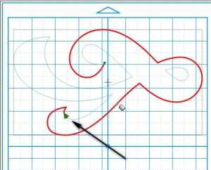
One thing not shown in the MTC video is how to quickly identify the location of a broken path. As I mentioned above, the blade will always start and end at the disconnected nodes. Thus, if you use the Measure Tools (bottom icon on the Node Edit menu), and then hover your mouse over the shape, a large blue or green arrow head will pop up indicating the cut direction and starting node for that particular path. Also check to see if the entire path has turned red:

If part of the path is only red, then you have another break on another part of the shape. Hover the mouse over another part of the shape to locate the break in that one. The following screen shots show that the outer shape has two breaks:


Thus, in this case, the closing would need to be applied in both locations. But as you can see from the video, it’s an easy process and you even have choices on how to close! Pick the one you like best and go with it!
Feel free to post if you have any questions…
by Sandy McCauley | May 8, 2012 | Auto-Tracing, Free Videos, Importing, Make The Cut, MTC
It’s been months and months since I posted about the 25 reasons to look into buying Make-The-Cut (MTC). Thus today, I’m catching up a bit by posting more reasons, all of them related to the auto-tracing functionality and why I prefer it over that in KNK or ACS Studio… or, for that matter, any of the other vector programs I’ve tried. This is one of the major reasons a lot of cutter owners have chosen Make-The-Cut and I have to tell you, in two simple words, “It Rocks!”
We last left off with #12 in my countdown to 25… which now will probably extend to 30 since I’ve had time to explore and discover more cool functionality available in MTC. So, we start the numbering of these seven new reasons with #13. Note that I also made a demo video to cover these 7 reasons, in case you prefer to just watch versus read! Also, there are additional details on the Pixel Trace function in the MTC user manuals here at this site, as well as in my free MTC training videos covering tracing.
Reason #13: Single Icon Access
In MTC, you only have to remember one location to activate the tracing, whether you are importing an image already saved as a file on your computer, scanning an image directly into MTC, or pasting an image that has been copied to your Windows Clipboard. The Pixel Trace function is located on a toolbar at the top of the MTC screen, easily accessible. If you prefer shortcut keys, then Ctrl+Shift+T will also activate Pixel Trace. Or you can activate in the File>Import menu. But again, what I like is that one window opens with three options available, as shown below:

My favorite method for finding images is to Google what I’m needing, click on “Images” on the left side of my browser window, click on an image I want, right click to select Copy, and then paste that image into MTC using Option 3 above. It doesn’t get any faster than that!
Reason #14: Preview of Results Before Accepting
After clicking on Open in the window above, I see the next reason I prefer to use MTC over KNK Studio: immediately the tracing I will get with the default settings appears. The blue lines show the path being traced while the green fill indicates what would be cut out using these settings. To the left, in black, I can also see the trace results, using the current settings, on the main MTC screen:

Further, as I modify settings to refine the trace, I can continue to see the effects of these settings without accepting the results. While this is standard in many vector programs, it is still the case, in KNK and ACS Studio, where you must accept each change in settings, leave the tracing functions, and move the original image away from the trace, before being able to see the results of that trace! Talk about tedious!
So, in this example, if I reduce the Threshold and increase the Resample in order to capture more detail of the flower, I can see the effects before accepting:

Reason #15: Viewing Settings
There are three settings which do not affect the trace in any way, but can be quite handy. First off, there is an Alpha setting which changes the visibility of the original graphic. Scroll to the far left and none of the original image shows and the user can better see exactly what will be cut. Scroll to the far right and more of the original graphic is visible in order to better see the fit of the trace lines around and within the image:

There is a Zoom function so that the user can zoom in on specific spots on the image to check the tracing. There is also a box to mark if the user wishes to view the nodes that would be produced with the current settings:

Reason #16:Useful Info about Imported Image and Traced Image
The lower left section of the Pixel Trace screen contains information about the original imported graphic, as well as the tracing itself:

The most useful data for me is noting the number of nodes and then the number of shapes. If there are thousands of nodes, then the file will take longer to cut. To reduce the nodes, the Resample setting should be decreased. If there are numerous shapes then I know I should increase the Despeckle to filter out tiny paths that are not necessary to my cut.
Reason #17:Texturize and Blackout Options
There are two typical situations in which I’m using the Pixel Trace function: (1) I need just a quick die cut shape or possibly a paper piecing of an image and (2) I want to perform a print and cut in which the original image will first be printed to my home printer and then my KNK will cut it out. In the second situation, I will typically be needing the original graphic to be imported and I only need the outside of the image traced. This is where the Texturize and Blackout options are useful.
The original graphic will not be imported unless the Texturize box is checked. Note how the original image now appears inside the tracing lines, to the left, in the main screen:

The Blackout option is used to delete any interior (child) paths contained within a larger path. Now, in this particular example, applying Blackout would delete the interior parts from being cut, which may or may not be wanted. But the nice thing is that the option to do this is there, if needed. Note that if you forget to do it, there’s a second Blackout tool on the Magic toolbar at the bottom:

Reason #18:Separate Tracing Option for Images with a Transparent Background
Images with transparent backgrounds can be more difficult to trace using the standard method in MTC. In the following example, a PNG file has been imported for a print and cut application. The default threshold is far from acceptable and even increasing it up to 200 still fails to complete trace this big cat! It was necessary to increase it up to 250 to get the best tracing:

But not to fret! Simply click on the Alpha tab and often the Default setting for the Threshold will give much closer desired results:

How does one know when to use this tab? Again, it’s applicable with files having transparent backgrounds, as found with many PNG files and especially when there are pale colors (such as yellow, gray, and white) next to the background.
Reason #19:Two Color Tracing Options
Most vector programs now have the option to provide color tracing, as well as monochrome tracing. But the uniqueness of MTC is that you have TWO separate color tracing options AND the ability to employ both of them, as well as the regular monochrome tracing, all during the same trace! Trace any part of your image, import it, and when asked if you want to trace more layers, answer, “Yes.” You can then stay with the same tracing option or click on another tab to use another tracing option! VERY cool!
Now this probably isn’t necessary for the majority of the tracings being done, but as I tell my students, “When tracing, you never really know what you’re going to need!”
The two colored options are the other two tabs in the Pixel Trace window, labelled “Palette” and “Color”. First let’s look at Palette in which the 16 most prevalent colors are identified and users can choose to select one or more at a time to be traced. In the following example I show two situations. In the first, only two of the four pink colors are marked. The pixels closest to those two colors are selected to be incorporated in the trace. In the second, all four pink colors are marked, resulting in more of the flowers being traced. Note how this results in a merging, of sorts, so that larger paths, incorporating more of the image, are created:

The Color tab allows one to use an eyedropper tool to move around the original image and then click to select a color to use in the tracing. The Tolerance setting is adjusted to then select how much of a similar color to include in the tracing. Below, the lighter pink is selected, but note the difference in what gets traced based on the whether the Tolerance is left at the default of 5 versus being lowered to 3:

Once the pink layer is imported, another color is then selected using the same eyedropper tool and then the Tolerance adjusted. Again, you can continue using this same Color method or switch to the Palette method! Either could be used for the black background OR the original Pixel tab could be employed instead. Or one could even use the Shadow function after leaving the trace window to create a background option! So many choices… so much fun!
Below are the results of the Palette trace and the Color trace, along with the original image… in some order? Can you tell which is which?

Make-The-Cut sells for $58.36 and will cut to a wide range of cutters, including the majority of the KNK models. Feel free to email me if you have any questions about using it with your particular cutter.
by Sandy McCauley | Apr 9, 2012 | Eraser, Free Files, Free Videos, Ginsu Knife, Inline, Inset Shadow, KNK, Make The Cut

Carol B contacted me asking for help with designing what I’m going to call a “shaped inset”. The original file was a onesie-shaped greeting card and she wanted to have a separate shape cut that would contain text for the inside of the card. She wanted it to be the same shape as the card but smaller so that there would be an even border or margin around the smaller shape, as shown in the screenshot above. Conveniently, I had another similar onesie file that I had designed several years ago, so I used it for experimenting and for making the videos for today’s post.
Since Carol was asking me how to do it in EITHER KNK Studio or Make The Cut, I decided to show how to do it in both programs since it is equally easy in both programs! In KNK Studio, I used the Ginsu Knife tool to bisect the card, followed by the Inline function under Transform>Outline to shrink the shape. This created a nice even border to appear around the smaller onesie shape. In Make The Cut, you will use the Erase tool to bisect the card, followed by the Inset Shadow function under the Shadow Layer to shrink the image, creating the same kind of border or margin.
Here are the links to the two videos:
Creating an Inset Shape from a Shaped Greeting Card in KNK Studio
Creating an Inset Shape from a Shaped Greeting Card in Make The Cut
If you want to follow along during the video and repeat exactly what you see, then the file I used can be downloaded here:
Onesie in KNK Format
Onesie in MTC Format


