Page 197 - KNK Groove with MTC User Manual
P. 197
This dot will now be flashing red
Again, click on these arrows or your keyboard
arrows until pin is on the reg mark corner.
Once the pin is centered on the reg mark
dot, click here or press Enter on your
keyboard.
After completing the third reg mark, the following window will open and remind you to wait until the pin has
returned to the origin before pressing OK.
IMPORTANT: If the pin moves vertically
down and is still aligned with the third reg
mark (instead of returning to the right
lower corner where you set the origin), you
will need to download an earlier version of
the KNK plugin. Please refer to the
Resources tab at www.knkusa.com.
Once you click on OK, the data will be sent and the arrow will be cut out.
Adjusting the Laser (Alignment Pin) Offset
After the print and cut is completed, examine how the cut lines were made relative to the printed lines. If the
offset is large enough, use a mm ruler to measure. If the offset is very small, then just estimating will be fine
as you refine your calibration.
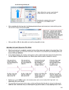
In the following diagram, the red lines represent the cut lines and the black lines represent the printed lines.
Use this diagram to determine whether your Offset values need to raised or lowered for your pin:
If th e red cut line is If the red cut line is If the red cut line is left If the red cut line is right
below the black print above the black print of the black print line, of the black print line,
line, then decrease the line, then increase the then increase the then decrease the value
value of X. value of X. value of Y. (Note: Y is of Y. (Note: Y is a
a negative number) negative number)
Red line is lower than Red line is higher than Red line is left of black line: Red line is 1mm right of
black line: change X black line: change X change Y from -10.0 to black line: change Y from
from 15.0 to 14.0. from 15.0 to 16.0. -9.0 (an increase to a -10.0 to -11.0 (a decrease
negative number). to a negative number).
Modify your X and Y Offset values in the window shown at the end of Section 9.02. Start with 1 mm
adjustments (like shown above).
It’s a good idea to keep track of prior values, so that you’ll know which direction to change for subsequent
calibration tests. Remember that you should expect to get perfect results, so keep adjusting those X and Y
197