Page 212 - Klic-N-Kut User Manual
P. 212
Adjusting the Laser Offset
After the print and cut is completed, examine how the cut lines were made relative to the printed lines. If the
offset is large enough, use a mm ruler to measure. If the offset is very small, then just estimating will be fine
as you refine your calibration.
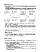
In the following diagram, the red lines represent the cut lines and the black lines represent the printed lines.
Use this diagram to determine whether your Offset values need to raised or lowered for your laser:
If the red cut line is If the red cut line is If the red cut line is left If the red cut line is right
below the black print above the black print of the black print line, of the black print line,
line, then decrease the line, then increase the then increase the then decrease the value
value of X. value of X. value of Y. (Note: Y is of Y. (Note: Y is a
a negative number) negative number)
Red line is lower than Red line is higher than Red line is left of black line: Red line is 1mm right of
black line: change X black line: change X change Y from -24.0 to black line: change Y from
from 0.3 to -0.7 (note: from 0.3 to 1.3 -23.0 (an increase to a -24.0 to -25.0 (a decrease
add negative sign) negative number). to a negative number).
Modify your X and Y Offset values in the window shown at the end of Section 9.02. Start with 1 mm
adjustments (like shown above). When entering a number less than 1, remember to include a 0. For
example, do not enter “.4”. Instead enter “0.4”.
It’s a good idea to keep track of prior values, so that you’ll know which direction to change for subsequent
calibration tests. Remember that you should expect to get perfect results, so keep adjusting those X and Y
values until you get there. After adjusting by 1 mm, you will need to adjust by 0.5 mm and even smaller to
get it perfect.
You may find that one side is aligned but the other is not. For example, the cut line may be perfectly aligned
with the print line on the lower side of the arrow but maybe 0.5 mm above the arrow along the upper side.
Adjust the calibration based on the side that is off.
Once the PNC is perfect, write down these X and Y values in case you buy a new computer or you have to
reformat your hard drive.
IMPORTANT: When you are ready to try this process on an actual raster image, don’t forget
to turn off the Wireframe option under File>Print Options.
9.05 Print and Cut Tips
When pixel tracing imported images, the trace lines will not necessarily be perfectly aligned with the image.
This can result in tiny bits of white appearing in certain spots, suggesting the PNC wasn’t accurate. Zoom in
close on the image so that you can see the trace line following the outline of the image. Look at the same
spots where the PNC didn’t follow the image perfectly. This could be the cause of the inaccurate PNC.
There are three ways of dealing with this situation:
Retrace the imported image, increasing the Resample setting. This will result in a tighter fit of the trace
line to the original graphic.
Use Node Editing and Segment Editing to move the trace lines to more closely fit the original graphic.
This is covered in detail in the last part of Section 7.13.
Create an inset line to use for cutting instead of the original trace line. This is presented in Section 9.06
– PNC with an Inset Cut Line.
212